
Two static wicks sit side by side… One ends in a scruffy, brush-like tuft of exposed fibers. The other is smooth, clean, almost polished.
Most people would replace the frayed one and reinstall the clean one, but as you will soon learn, those frayed edges play an important role.
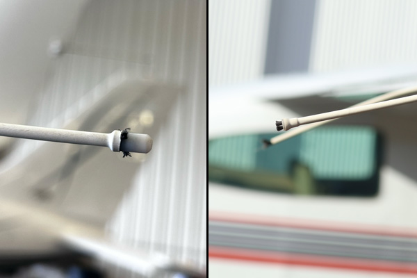
On many flexible general aviation wicks, that frayed tuft is the component working exactly as designed—while the smooth tip means the conductive fibers that dissipate static electricity have eroded away.
Knowing the difference matters. An aircraft static wick, also called a static discharger, is not simply a rod attached to a trailing edge. Its mounting, protective coating, conductive material, discharge tip, resistance, and electrical connection all contribute to its performance.
A useful inspection therefore asks more than, “Is the wick still attached?” It asks whether the complete component still appears capable of performing its intended role within the aircraft’s static discharging system.
What Does a Static Wick Do?
As an aircraft flies through rain, snow, ice crystals, dust, and other particles, static electricity accumulates on the airframe. When the aircraft’s electrical potential rises high enough, that charge leaves through what is known as corona discharge. A properly designed static discharging system provides many small, controlled discharge points so the release happens at lower intensity, avoiding interference with sensitive aircraft systems.
The full physics and characteristics of precipitation static, the corona effect, why aircraft carry multiple wicks, and how flexible and rigid designs differ are covered in the companion article: What Is an Aircraft Static Wick—and How Does It Reduce Interference?
For inspection purposes, the key lesson is this: a static wick can remain physically present while losing the features that allow it to dissipate electrical charge effectively.
Begin With the Correct Static Discharger Design
Before deciding whether a static wick looks normal, identify what type of wick you are inspecting. Aircraft may use:
- Flexible wicks with exposed conductive fibers
- Semi-rigid dischargers
- Rigid high-speed dischargers
- Replaceable wick-and-base combinations
- Integrated discharger assemblies
- Different metallic, carbon, or composite discharge tips
Not every static wick should have a frayed end. Not every wick should flex. Not every exposed conductive surface indicates damage. The acceptable appearance depends on the component’s design.
Aircraft maintenance information, the illustrated parts catalog, manufacturer instructions, and the installed part number should establish what belongs on the aircraft. This is especially important on older airplanes: a previous replacement may have introduced a superseded or alternate configuration—or an incorrect component may have been installed simply because it fit the existing base.
A physical match is not enough. Static dischargers can differ in resistance, length, materials, airspeed capability, altitude capability, and intended discharge behavior.
Inspect the Exposed Fibers on Flexible Static Wicks
Many general aviation aircraft use flexible static wicks with conductive fibers exposed at the trailing end. These fibers commonly appear frayed, uneven, or brush-like—and that appearance is intentional. Each fine fiber is a deliberate corona point; the companion article explains why dividing the discharge among many frayed points reduces its intensity.
During inspection, look for a recognizable bundle of exposed conductive fibers on flexible wicks designed to use them. Potential concerns include:
- Few or no fibers remaining
- A smooth or blunt end where fibers should be visible
- A substantially shortened fiber bundle
- Fibers covered by paint, coating, sealant, or contamination
- Severe damage to the discharge end
- A tip that differs noticeably from comparable serviceable wicks
A common mistake is assuming that a smooth-looking end is preferable to a frayed one. On this type of static discharger, the opposite may be true. The exposed fibers are functional discharge points; when they wear away, the wick may no longer divide the corona discharge as designed.
Do not pull, trim, spread, or manipulate the fibers simply to improve their appearance. Suspected damage should be evaluated using the applicable maintenance information.
Examine the Protective Outer Coating
Flexible static wicks commonly have a protective coating surrounding their conductive material. This coating protects the wick from weather, moisture, erosion, sunlight, and handling damage. It also helps control where electrical charge reaches the atmosphere: the intended discharge should occur at the designed tip—not through random openings elsewhere on the wick.
Inspect the entire coating under good lighting. Look for:
- Cracks
- Splits
- Cuts
- Abrasion
- Peeling
- Flaking
- Blistering
- Missing sections
- Severe weathering
- Surface erosion
- Conductive material exposed away from the intended discharge tip
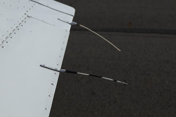
A minor surface mark is not automatically grounds for replacement, but cracking or erosion should not be dismissed as cosmetic. If conductive material becomes exposed at an unintended location, it may create an additional point from which electrical charge can leave, potentially moving electrical activity closer to the airframe or antenna fields. The applicable aircraft or component criteria should determine whether a particular defect is permissible.
Look for Erosion and Shortening
Static wicks project into the airflow and are continually exposed to rain, ice particles, dust, cleaning, handling, and aerodynamic loads. Over time, this exposure can erode both the discharge end and the protective coating.
Compare the wick with:
- The same type of wick at another location
- The corresponding wick on the opposite side of the aircraft
- A known serviceable replacement
- Manufacturer illustrations
- Published dimensions or service limits
Possible warning signs include an unusually short wick, a shortened or missing fiber bundle, a rounded or polished tip where fibers should be exposed, uneven wear, material loss along one side, erosion deep enough to compromise the coating, or a profile that differs from comparable wicks.
Comparison is useful, but it should not be the only standard. Two wicks may be similarly worn, and a legitimate replacement configuration may look different from the original design. Dimensions, part numbers, and maintenance limits provide better evidence than appearance alone.
Check for Bending, Kinking, and Structural Damage
Flexible static wicks are designed to flex. That does not mean every bend is acceptable. Inspect for permanent deformation, sharp kinks, crushed areas, partial separation, or evidence that the wick has been struck.
Static wicks are frequently damaged on the ground because they extend beyond the wing or tail and may be located close to eye level. Common sources of damage include hangar doors, maintenance stands, aircraft covers, cleaning equipment, tools, clothing, tow equipment, and people walking around the aircraft.
On rigid dischargers, bending deserves particular attention. A rigid wick is designed to maintain a specific position in the airflow; a visibly bent unit may no longer preserve the intended relationship between its discharge tip, the airframe, and nearby antenna fields.
Possible signs of physical damage include:
- A sharp bend instead of a natural curve
- A kink in a flexible wick
- A rigid wick misaligned with comparable units
- Cracking near the point of deformation
- Separation from the base
- A wick that rotates when it should remain secure
- Impact marks
- Damage where the wick enters its mounting fitting
Do not attempt to straighten a damaged static discharger unless an approved procedure specifically permits it.
Inspect the Mounting Base
A serviceable wick attached to a damaged or poorly connected base may not function correctly. The mounting base secures the static discharger and helps establish the electrical path between the wick and airframe. Depending on the design, the wick may thread into the base, lock into it, attach with hardware, or be incorporated into an integrated assembly.
Inspect for:
- Loose attachment
- Missing hardware
- Corrosion
- Cracking
- Distortion
- Impact damage
- Rotation or movement
- Evidence of arcing
- Paint or contamination at the mounting interface
- Damage to the surrounding aircraft structure
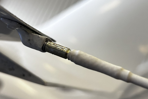
A loose base can create both mechanical and electrical problems. It may allow vibration, alter the wick’s position, interrupt conductivity, or permit the component to separate in flight. Some wicks can be replaced separately from their bases, while others use integrated configurations—confirm the actual arrangement before ordering parts.
Confirm That All Required Wicks Are Present
One of the simplest inspection steps is also one of the most important: verify that no static dischargers are missing. Typical installation locations may include the ailerons, wing trailing edges, elevator, horizontal stabilizer, rudder, vertical stabilizer, and other manufacturer-specified locations.
A missing wick may leave an empty base or damaged fitting, but the absence may not be obvious unless the inspector knows a wick belongs there. Do not assume the remaining wicks can fully compensate: FAA guidance is explicit that sufficient dischargers must be installed to carry the required electrical current and keep the airframe potential below the corona threshold of uncontrolled trailing edges. 1
Verify the required number and locations using aircraft documentation rather than comparing the aircraft with another airplane on the ramp.
Serial number matters here. Some models still in production were built for years before static dischargers were added to the type design. On an early aircraft, the absence of wicks may reflect its original, correct configuration rather than a discrepancy—while a later serial of the same model may require a full complement. Conversely, if dischargers were added to an early aircraft at some point, the installation documentation defines what should now be present. The aircraft’s own records and serial-applicable documentation are the standard, not the current production version of the model.
Do Not Overlook Aircraft Bonding
Static wicks are the final discharge points—but electrical charge must still be able to travel to them. Why bonding matters electrically, and how charge moves through the airframe toward the discharge locations, is explained in the companion article. During inspection, control surfaces deserve particular attention because their hinges may not provide sufficiently reliable electrical conductivity; bonding straps connect those movable components to the rest of the airframe.
Possible concerns include:
- Broken bonding straps
- Frayed or corroded bonding material
- Loose attachment points
- Missing hardware
- Contaminated surfaces
- Paint affecting electrical contact
- Damage near hinges
- Excessive resistance
A pilot’s visual inspection may reveal an obviously broken strap, but determining bonding effectiveness can require resistance testing and approved maintenance procedures. FAA technical guidance notes that discharges can occur between metallic components that are not properly bonded and that static dischargers require a low-resistance connection to the airframe. 2
Treat New Radio Noise as a Clue
Static-discharge problems are sometimes discovered in the cockpit before they are identified during an inspection. A pilot may notice:
- Hissing that increases in precipitation
- Crackling or popping in the headset
- Weak radio reception in rain or snow
- Noise affecting more than one receiver
- Interference that ends after leaving precipitation
- Degraded navigation reception
- A new problem following painting or maintenance
These symptoms do not prove that a static wick is defective. Similar interference can originate in radios, ignition systems, alternators, wiring, lighting, antennas, or other electrical equipment. The circumstances matter: noise that develops primarily in precipitation and changes with atmospheric conditions is consistent with P-static, which FAA reports associate with effects ranging from unusual audio noise and weak reception to significant communication and avionics disruption. 1
Record the conditions as precisely as possible, including weather, precipitation type, airspeed, affected equipment, phase of flight, noise intensity, and whether the condition disappeared after leaving the weather.
Preventing Static Wick Damage—and Protecting People
The best time to protect a static wick is before someone walks into it or knocks it off. Because wicks extend from trailing edges and may be positioned near face level, they can be difficult to see in a crowded hangar, on a dim ramp, or while someone is concentrating on another maintenance task.
The yellow Aero-Mach Wilco static wick protector slips over the tip of a wick and serves two purposes during ground operations:
- It makes the static wick more visible.
- It provides a soft barrier between the pointed wick and anyone walking or working nearby.
That can help protect the wick from accidental contact while also reducing the risk of someone being poked in the face or eye. Aero-Mach Wilco identifies the Wick Watch as a bright, waterproof EVA-foam protector designed to increase visibility and protect static wicks during ground operations, and it is listed as approved for use with TCO static wicks while the aircraft is on the ground. 3
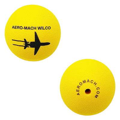
Good practices include installing protectors when the airplane is parked in a busy hangar, undergoing maintenance, being cleaned, or displayed where people may walk close to its wings and tail.
However, a Wick Watch is strictly a ground-use product. It must be removed before flight: a protector left over the tip would cover the intended discharge area and could create an aerodynamic hazard. Aero-Mach Wilco specifically warns that static-wick protectors must never remain installed during flight. [3] Consider adding protector removal to the aircraft’s preflight flow whenever they are used.
When Does a Static Wick Need Replacement?
A static wick should be evaluated for replacement when it has lost or damaged a feature necessary for its intended function. Common indicators include:
- The wick is missing.
- Required conductive fibers have worn away.
- The tip is blunt on a design that should have exposed fibers.
- The protective coating is cracked, split, peeling, or severely eroded.
- Conductive material is exposed at an unintended location.
- The wick is permanently bent or kinked.
- A rigid discharger no longer holds its intended alignment.
- The wick or base is loose.
- The base is corroded, cracked, distorted, or damaged.
- The component fails an applicable resistance or continuity test.
- The wick no longer meets dimensional or service limits.
- An incorrect part number or configuration is installed.
These are inspection indicators rather than universal maintenance limits. The applicable aircraft and component documentation governs the final determination. A worn static discharger should not be restored through improvised trimming, recoating, splicing, fiber replacement, or reshaping unless an authorized procedure specifically permits that work.
Selecting the Correct Replacement Static Wick
Aero-Mach TCO has manufactured electrostatic dischargers for aircraft manufacturers since 1973, supporting current-production and legacy applications; replacement TCO wicks, bases, and integrated dischargers are available to owners, operators, fleets, and maintenance organizations through the Aero-Mach Wilco TCO Static Wick catalog. 4 5
Begin with the installed part number and aircraft documentation. Useful identification information may include:
- Aircraft make and model
- Aircraft serial number
- Installed wick part number
- Base part number
- Installation location
- Photographs
- Dimensions
- Attachment style
- Flexible or rigid construction
- Aircraft operating speed
- Applicable illustrated-parts information
Static dischargers that appear physically similar may have different resistance values, lengths, altitude capabilities, airspeed limits, or intended applications. Where aircraft eligibility is uncertain, consult the applicable maintenance documentation and appropriately authorized maintenance personnel.
A Frayed Wick May Be Healthy—and a Smooth One May Not Be
Static-wick inspections demonstrate why appearance must be interpreted in the context of function. On a flexible general aviation wick, a frayed bundle of exposed conductive fibers may be exactly what the design requires. A smooth end may indicate that those fibers have eroded away. A small crack in the protective coating may create an unintended discharge location. A perfectly clean wick may be electrically isolated by corrosion at its base. A replacement that fits may still have the wrong resistance or operating capability.
A meaningful inspection therefore considers the correct wick design, the intended discharge tip, fiber condition, coating integrity, physical alignment, mounting security, base condition, aircraft bonding, the required number of wicks, and the correct replacement application.
Frequently Asked Questions
How can you tell if a static wick is bad?
Look for missing or eroded discharge fibers, a blunt tip on a design that should have exposed fibers, cracked or peeling coating, permanent bends or kinks, a loose wick or base, corrosion, or failure of an applicable resistance test. The aircraft’s maintenance documentation governs the final determination.
Should a static wick look frayed?
On many flexible general aviation designs, yes—the exposed fiber bundle is functional, not damaged. But not every discharger uses exposed fibers; rigid and integrated designs have different tips. Identify the installed part number before judging appearance.
How often should static wicks be replaced?
There is no universal replacement interval. Static wicks are replaced on condition—when inspection reveals worn fibers, coating damage, physical deformation, mounting problems, or a failed resistance check—in accordance with the applicable aircraft and component documentation.
Can you repair a worn static wick?
Generally no. Trimming, recoating, splicing, or reshaping a discharger is not appropriate unless an approved procedure specifically permits that work. Worn wicks are normally replaced, using the correct part number for the aircraft and installation location.
Can an aircraft fly with a missing static wick?
That depends on the aircraft’s documentation, any applicable minimum equipment list, and an airworthiness determination by authorized personnel. FAA guidance is clear that the system needs sufficient dischargers to function as designed, so a missing wick should be evaluated before flight rather than assumed harmless. 1
Once you can spot a worn wick, one question remains: why does the loss of a few tiny fibers change what a pilot hears in the headset?
The answer lies in what happens at the exact moment static electricity leaves the aircraft. Read What Is an Aircraft Static Wick—and How Does It Reduce Interference? for that explanation.
References
- FAA Aeronautical Information Manual, Chapter 7, Section 6 — Safety of Flight
- FAA Advisory Circular AC 43-206 CHG 1
- Aero-Mach Wilco Wick Watch Static Wick Protector
- Industry Leading Electrostatic Dischargers | Aero-Mach TCO
- TCO Static Wicks | Aero-Mach Wilco
Technically reviewed by Aero-Mach TCO engineering staff.